A detailed account of repairing a Commodore PET computer from 1977, involving diagnosing multiple bad chips and using adapter boards to replace obsolete ROMs.
<style>
code {font-size: 100%; font-family: courier, fixed;}
</style>
<p><title>mult3</title></p>
<p>In 1977, Commodore released the PET computer, a quirky home computer that combined the processor,
a tiny keyboard, a cassette drive for storage, and a trapezoidal screen in a metal unit.
The Commodore PET, the Apple II, and Radio Shack's TRS-80 started the home computer market with ready-to-run computers,
systems that were called in retrospect the
<a href="https://web.archive.org/web/20080618072507/http://www.byte.com/art/9509/sec7/art15.htm">1977 Trinity</a>.
I did much of my early programming on the PET, so when someone offered me a non-working PET a few years
ago, I took it for nostalgic reasons.</p>
<p>You'd think that a home computer would be easy to repair, but it turned out to be a challenge.
The chips in early PETs are notorious for failures and, sure enough, we found multiple bad chips.
Moreover, these RAM and ROM chips were special designs that are mostly unobtainable now.
In this post, I'll summarize how we repaired the system, in case it helps anyone else.</p>
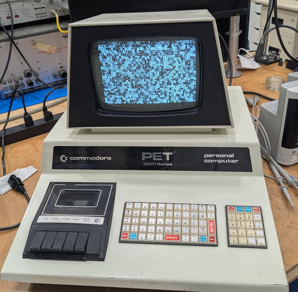
<p>When I first powered up the computer, I was greeted with a display full of random characters.
This was actually reassuring since it showed that most of the computer was working: not just the monitor,
but the video RAM, character ROM, system clock, and power supply were all operational.</p>
<p><a href="https://static.righto.com/images/pet/garbage-screen.jpg"><img alt="The Commodore PET started up, but the screen was full of garbage." class="hilite" height="489" src="https://static.righto.com/images/pet/garbage-screen-w500.jpg" title="The Commodore PET started up, but the screen was full of garbage." width="500" /></a><div class="cite">The Commodore PET started up, but the screen was full of garbage.</div></p>
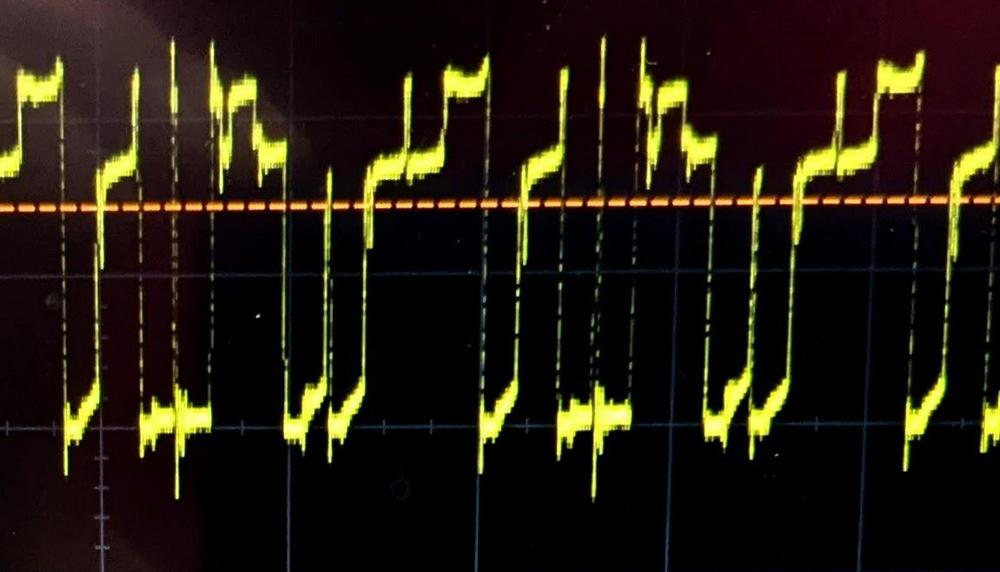
<p>With an oscilloscope, I examined signals on the system bus and found that the clock, address, and data lines were full of activity,
so the 6502 CPU seemed to be operating.
However, some of the data lines had three voltage levels, as shown below.
This was clearly not good, and suggested that a chip on the bus was messing up the data signals.</p>
<p><a href="https://static.righto.com/images/pet/scope.jpg"><img alt="The scope shows three voltage levels on the data bus." class="hilite" height="286" src="https://static.righto.com/images/pet/scope-w500.jpg" title="The scope shows three voltage levels on the data bus." width="500" /></a><div class="cite">The scope shows three voltage levels on the data bus.</div></p>
<p>Some helpful sites online<span id="fnref:troubleshooting"><a class="ref" href="#fn:troubleshooting">7</a></span> suggested that if a PET gets stuck before clearing the screen, the most likely cause is
a failure of a system ROM chip.
Fortunately, Marc has a <a href="https://americanretro.shop/rctp">Retro Chip Tester</a>, a cool device designed to
test vintage ICs: not just 7400-series logic, but vintage RAMs and ROMs.
Moreover, the tester knows the correct ROM contents for a ton of old computers, so it can tell if a PET ROM has
the right contents.</p>
<p>The Retro Chip Tester showed that two of the PET's seven ROM chips had failed.
These chips are MOS Technologies MPS6540, a 2K×8 ROM with a weird design that is incompatible with standard ROMs.
Fortunately, several people make adapter boards that let you substitute a standard 2716 EPROM, so I ordered
two adapter boards, assembled them, and Marc programmed the 2716 EPROMs from online data files.
The 2716 EPROM requires a bit more voltage to program than Marc's programmer supported, but the chips seemed to
have the right contents (foreshadowing).</p>
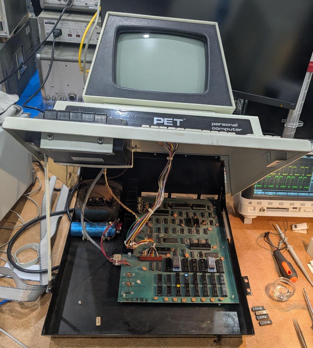
<p><a href="https://static.righto.com/images/pet/pet-opened.jpg"><img alt="The PET opened, showing the motherboard." class="hilite" height="556" src="https://static.righto.com/images/pet/pet-opened-w500.jpg" title="The PET opened, showing the motherboard." width="500" /></a><div class="cite">The PET opened, showing the motherboard.</div></p>
<p>The PET's case swings open with an arm at the left to hold it open like a car hood.
The first two rows of chips at the front of the motherboard are the RAM chips.
Behind the RAM are the seven ROM chips; two have been
replaced by the ROM adapter boards.
The 6502 processor is the large black chip behind the ROMs, toward the right.</p>
<p>With the adapter boards in place, I powered on the PET with great expectations of success, but it failed in precisely
the same way as before, failing to clear the garbage off the screen.
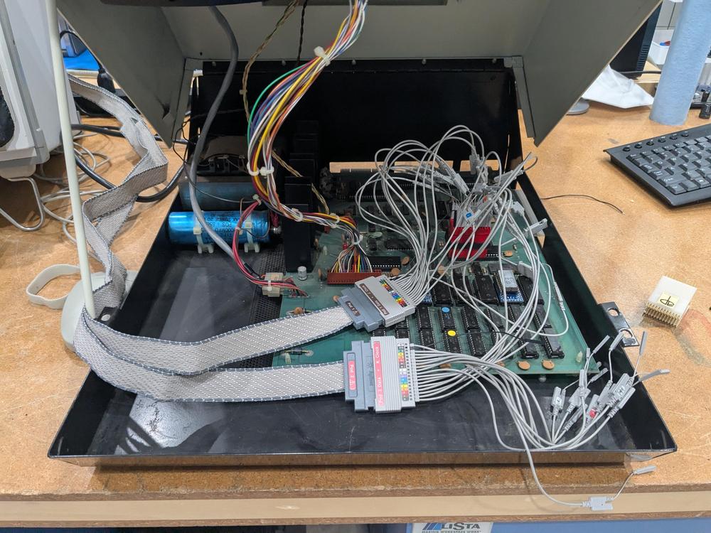
Marc decided it was time to use his Agilent 1670G logic analyzer to find out what was going on;
(Dating back to 1999, this logic analyzer is modern by Marc's standards.)
He wired up the logic analyzer to the 6502 chip, as shown below, so we could track the address bus, data bus,
and the read/write signal.
Meanwhile, I disassembled the ROM contents using Ghidra, so I could interpret the logic analyzer against the assembly code.
(<a href="https://ghidra-sre.org/">Ghidra</a> is a program for reverse-engineering software that was developed by the NSA, strangely enough.)</p>
<p><a href="https://static.righto.com/images/pet/logic-analyzer.jpg"><img alt="Marc wired up the logic analyzer to the 6502 chip." class="hilite" height="375" src="https://static.righto.com/images/pet/logic-analyzer-w500.jpg" title="Marc wired up the logic analyzer to the 6502 chip." width="500" /></a><div class="cite">Marc wired up the logic analyzer to the 6502 chip.</div></p>
<p>The logic analyzer provided a trace of every memory access from the 6502 processor, showing what it was executing.
Everything went well for a while after the system was turned on:
the processor
jumped to the reset vector location, did a bit of initialization, tested the memory, but then everything went haywire.
I noticed that the memory test failed on the first byte.
Then the software tried to get more storage by garbage collecting the BASIC program and variables.
Since there wasn't any storage at all, this didn't go well and the system hung before reaching the code that
clears the screen.</p>
<p>We tested the memory chips, using the Retro Chip Tester again, and found three bad chips.
Like the ROM chips, the RAM chips are unusual: MOS Technology <a href="http://blog.tynemouthsoftware.co.uk/2024/06/mos-6550-ram-chips.html">6550</a> static RAM chip, 1K×4.
By removing the bad chips and shuffling the good chips around, we reduced the 8K PET to a 6K PET.
This time, the system booted, although there was a mysterious 2×2 checkerboard symbol near the middle of the screen (foreshadowing).
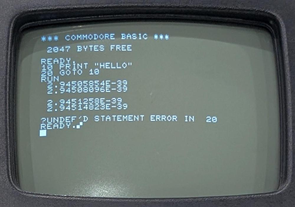
I typed in a simple program to print "HELLO", but the results were very strange: four floating-point numbers, followed
by a hang.</p>
<p><a href="https://static.righto.com/images/pet/floats.jpg"><img alt="This program didn't work the way I expected." class="hilite" height="351" src="https://static.righto.com/images/pet/floats-w500.jpg" title="This program didn't work the way I expected." width="500" /></a><div class="cite">This program didn't work the way I expected.</div></p>
<p>This behavior was very puzzling.
I could successfully enter a program into the computer, which exercises a lot of the system code.
(It's not like a terminal, where echoing text is trivial; the PET does a lot of processing behind the scenes to parse
a BASIC program as it is entered.)
However, the output of the program was completely wrong, printing floating-point numbers instead of a string.</p>
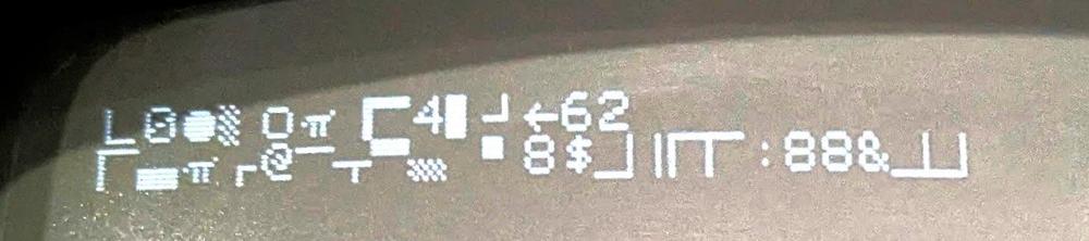
<p>We also encountered an intermittent problem that after turning the computer on,
the boot message would be complete gibberish, as shown below.
Instead of the "*** COMMODORE BASIC ***" banner, random characters and graphics would appear.</p>
<p><a href="https://static.righto.com/images/pet/bad-boot.jpg"><img alt="The garbled boot message." class="hilite" height="111" src="https://static.righto.com/images/pet/bad-boot-w500.jpg" title="The garbled boot message." width="500" /></a><div class="cite">The garbled boot message.</div></p>
<p>How could the computer be operating well for the most part, yet also completely wrong?
We went back to the logic analyzer to find out.</p>
<p>I figured that the gibberish boot message would probably be the easiest thing to track down, since that happens
early in the boot process.
Looking at the code, I discovered that after the software tests the memory, it converts the memory size to an ASCII string using a moderately complicated
algorithm.<span id="fnref:conversion"><a class="ref" href="#fn:conversion">1</a></span>
Then it writes the system boot message and the memory size to the screen. </p>
<p>The PET uses a subroutine to write text to the screen.
A pointer to the text message is held in memory locations 0071 and 0072.
The assembly code below stores the pointer (in the X and Y registers) into these memory locations.
(This Ghidra output
shows the address, the instruction bytes, and the symbolic assembler instructions.)</p>
<pre>
d5ae 86 71 STX 71
d5b0 84 72 STY 72
d5b2 60 RTS
</pre>
<p>For the code above, you'd expect the processor to read the instruction bytes 86 and 71, and then write to address 0071.
Next it should read the bytes 84 and 72 and write to address 0072.
However, the logic analyzer output below showed that something slightly different happened.
The processor fetched instruction bytes 86 and 71 from addresses D5AE and D5AF,
then wrote 00 to address 0071, as expected.
Next, it fetched instruction bytes 84 and 72 as expected, but wrote 01 to address 007A, not 0072!</p>
<pre>
step address byte read/write'
112235 D5AE 86 1
112236 D5AF 71 1
112237 0071 00 0
112238 D5B0 84 1
112239 D5B1 72 1
112240 <span style="background-color: yellow">007A</span> 01 0
</pre>
<p>This was a smoking gun. The processor had messed up and there was a one-bit error in the address.
Maybe the 6502 processor issued a bad signal or maybe something else was causing problems on the bus.
The consequence of this error was that the string pointer referenced random memory rather than the desired boot
message, so random characters were written to the screen.</p>
<p>Next, I investigated why the screen had a mysterious checkerboard character.
I wrote a program to scan the logic analyzer output to extract all the writes to screen memory.
Most of the screen operations made sense—clearing the screen at startup and then writing the boot message—but I found one
unexpected write to the screen.
In the assembly code below, the Y register should be written to zero-page address 5e, and the X register should
be written to the address 66, some locations used by the BASIC interpreter.</p>
<pre>
d3c8 84 5e STY 5e
d3ca 86 66 STX 66
</pre>
<p>However, the logic analyzer output below showed a problem.
The first line should fetch the opcode 84 from address d3c8, but the processor received the opcode 8c from the ROM,
the instruction to write to a 16-bit address.
The result was that instead of writing to a zero-page address, the 6502 fetched another byte to write to a 16-bit
address.
Specifically, it grabbed the STX instruction (86) and used that as part of the address, writing FF (a checkerboard character) to screen memory at
865E<span id="fnref:screen"><a class="ref" href="#fn:screen">2</a></span> instead of to the BASIC data structure at 005E.
Moreover, the STX instruction wasn't executed, since it was consumed as an address.
Thus, not only did a stray character get written to the screen, but data structures in memory didn't get updated.
It's not surprising that the BASIC interpreter went out of control when it tried to run the program.</p>
<pre>
step address byte read/write'
186600 D3C8 <span style="background-color: yellow">8C</span> 1
186601 D3C9 <span style="background-color: cyan">5E</span> 1
186602 D3CA <span style="background-color: cyan">86</span> 1
186603 <span style="background-color: cyan">865E</span> FF 0
</pre>
<p>We concluded that a ROM was providing the wrong byte (8C) at address D3C8.
This ROM turned out to be one of our replacements; the under-powered EPROM programmer had resulted in a flaky byte.
Marc re-programmed the EPROM with a more powerful programmer.
The system booted, but with much less RAM than expected.
It turned out that <em>another</em> RAM chip had failed.</p>
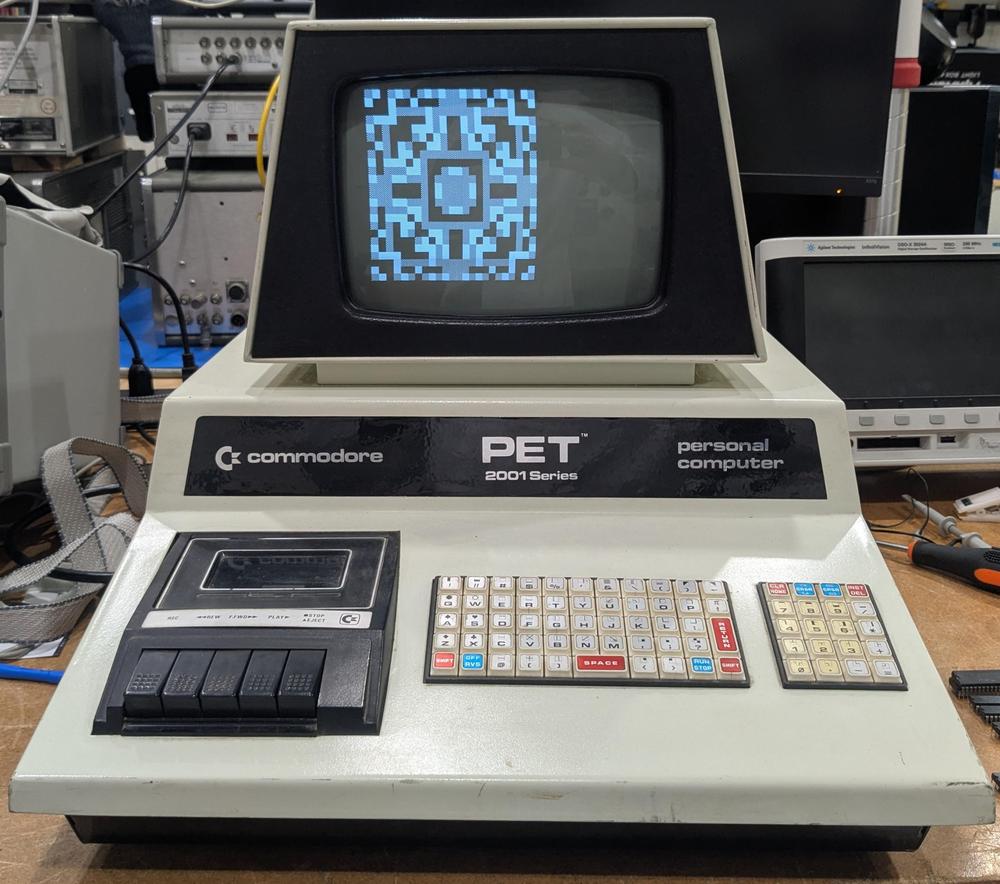
<p>Finally, we got the PET to run. I typed in a simple program to generate an animated graphical pattern, a program
I remembered from when I was about 13<span id="fnref:listing"><a class="ref" href="#fn:listing">3</a></span>, and generated this output:</p>
<p><a href="https://static.righto.com/images/pet/pet-working.jpg"><img alt="Finally, the PET worked and displayed some graphics. Imagine this pattern constantly changing." class="hilite" height="442" src="https://static.righto.com/images/pet/pet-working-w500.jpg" title="Finally, the PET worked and displayed some graphics. Imagine this pattern constantly changing." width="500" /></a><div class="cite">Finally, the PET worked and displayed some graphics. Imagine this pattern constantly changing.</div></p>
<p>In retrospect, I should have tested all the RAM and ROM chips at the start, and we probably could have found the faults
without the logic analyzer.
However, the logic analyzer gave me an excuse to learn more about Ghidra and the PET's assembly code, so it
all worked out in the end.<span id="fnref:why"><a class="ref" href="#fn:why">4</a></span></p>
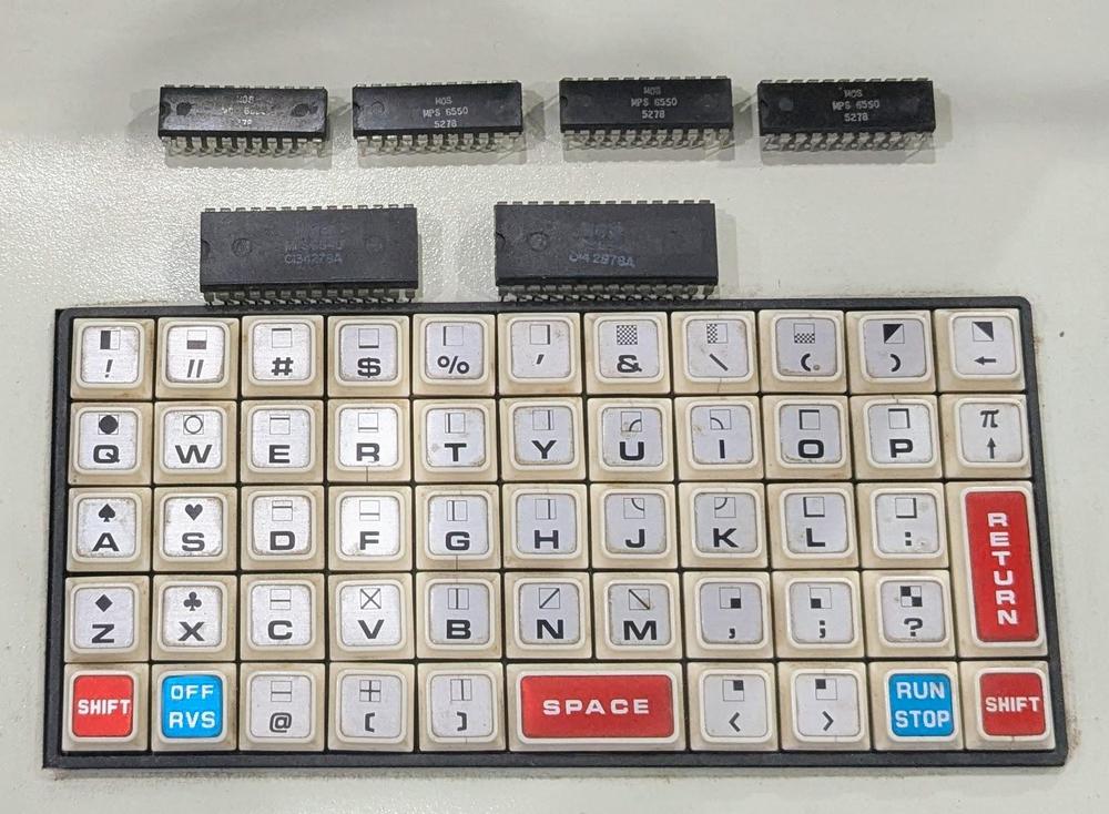
<p><a href="https://static.righto.com/images/pet/bad-chips.jpg"><img alt="The bad chips sitting on top of the keyboard." class="hilite" height="367" src="https://static.righto.com/images/pet/bad-chips-w500.jpg" title="The bad chips sitting on top of the keyboard." width="500" /></a><div class="cite">The bad chips sitting on top of the keyboard.</div></p>
<p>In the end, the PET had 6 bad chips: two ROMs and four RAMs.
The 6502 processor itself turned out to be fine.<span id="fnref:6502"><a class="ref" href="#fn:6502">5</a></span>
The photo below shows the 6 bad chips on top of the PET's tiny keyboard.
On the top of each key, you can see the quirky graphical character set known as PETSCII.<span id="fnref:petscii"><a class="ref" href="#fn:petscii">6</a></span>
As for the title, I'm counting the badly-programmed ROM as half a bad chip since
the chip itself wasn't bad but it was functioning erratically.</p>
<p>CuriousMarc created a video of the PET restoration, if you want more:</p>
<iframe width="560" height="315" src="https://www.youtube.com/embed/nxilekpLp6g?si=1ZJdrJWexW8T5wwz" title="YouTube video player" frameborder="0" allow="accelerometer; autoplay; clipboard-write; encrypted-media; gyroscope; picture-in-picture; web-share" referrerpolicy="strict-origin-when-cross-origin" allowfullscreen></iframe>
<p>Follow me on Bluesky (<a href="https://bsky.app/profile/righto.com">@righto.com</a>) or <a href="https://www.righto.com/feeds/posts/default">RSS</a> for updates. (I'm no longer on Twitter.)
Thanks to Mike Naberezny for providing the PET.
Thanks to <a href="https://bsky.app/profile/tubetime.bsky.social">TubeTime</a>, Mike Stewart, and especially
<a href="https://www.youtube.com/CuriousMarc">CuriousMarc</a> for help with the repairs.
Some useful PET troubleshooting links are in the footnotes.<span id="fnref2:troubleshooting"><a class="ref" href="#fn:troubleshooting">7</a></span></p>
<h2>Footnotes and references</h2>
<div class="footnote">
<ol>
<li id="fn:conversion">
<p>Converting a number to an ASCII string is somewhat complicated on the 6502. You can't quickly divide by 10 for
the decimal conversion, since the processor doesn't have a divide instruction.
Instead, the PET's conversion routine has hard-coded four-byte constants: -100000000, 10000000, -100000, 100000, -10000, 1000, -100, 10, and -1.
The routine repeatedly adds the first constant (i.e. subtracting 100000000) until the result is negative.
Then it repeatedly adds the second constant until the result is positive, and so forth.
The number of steps gives each decimal digit (after adjustment).</p>
<p>The same algorithm is used with the base-60 constants: -2160000, 216000, -36000, 3600, -600, and 60.
This converts the uptime count into hours, minutes, and seconds for the <code>TIME$</code> variable. (The PET's basic time count is the "jiffy",
1/60th of a second.) <a class="footnote-backref" href="#fnref:conversion" title="Jump back to footnote 1 in the text">↩</a></p>
</li>
<li id="fn:screen">
<p>Technically, the address 865E is not part of screen memory, which is 1000 characters starting at address 0x8000.
However, the PET's address uses some shortcuts in address decoding, so 865E ends up the same as 825e, referencing
the 7th character of the 16th line. <a class="footnote-backref" href="#fnref:screen" title="Jump back to footnote 2 in the text">↩</a></p>
</li>
<li id="fn:listing">
<p>Here's the source code for my demo program, which I remembered from my teenage programming.
It simply displays blocks (black, white, or gray) with 8-fold symmetry,
writing directly to screen memory with <code>POKE</code> statements.
(It turns out that almost anything looks good with 8-fold symmetry.)
The cryptic heart in the first <code>PRINT</code> statement is the clear-screen character.</p>
<p><a href="https://static.righto.com/images/pet/listing.jpg"><img alt="My program to display some graphics." class="hilite" height="284" src="https://static.righto.com/images/pet/listing-w400.jpg" title="My program to display some graphics." width="400" /></a><div class="cite">My program to display some graphics.</div></p>
<p><!-- --> <a class="footnote-backref" href="#fnref:listing" title="Jump back to footnote 3 in the text">↩</a></p>
</li>
<li id="fn:why">
<p>So why did I suddenly decide to restore a PET that had been sitting in my garage since 2017?
Well, CNN was filming an interview with Bill Gates
and they wanted background footage of the 1970s-era computers that ran the Microsoft BASIC that Bill Gates
wrote.
Spoiler: I didn't get my computer working in time for CNN, but Marc found some other computers.</p>
<p><iframe width="560" height="315" src="https://www.youtube.com/embed/TTicRvHz6Hs?si=l8FUAI8ufFHcIMDI&start=1872" title="YouTube video player" frameborder="0" allow="accelerometer; autoplay; clipboard-write; encrypted-media; gyroscope; picture-in-picture; web-share" referrerpolicy="strict-origin-when-cross-origin" allowfullscreen></iframe></p>
<p><!-- --> <a class="footnote-backref" href="#fnref:why" title="Jump back to footnote 4 in the text">↩</a></p>
</li>
<li id="fn:6502">
<p>I suspected a problem with the 6502 processor because the logic analyzer showed that the 6502 read an instruction correctly
but then accessed the wrong address.
Eric provided a replacement 6502 chip but
swapping the processor had no effect.
However, reprogramming the ROM fixed both problems.
Our theory is that the signal on the bus either had a timing problem or a voltage problem, causing the logic analyzer
to show the correct value but the 6502 to read the wrong value.
Probably the ROM had a weakly-programmed bit, causing the ROM's output for that bit to either be at an intermediate
voltage or causing the output to take too long to settle to the correct voltage.
The moral is that you can't always trust the logic analyzer if there are analog faults. <a class="footnote-backref" href="#fnref:6502" title="Jump back to footnote 5 in the text">↩</a></p>
</li>
<li id="fn:petscii">
<p>The PETSCII graphics characters are now in Unicode in the <a href="https://en.wikipedia.org/wiki/Symbols_for_Legacy_Computing">Symbols for Legacy Computing</a> block. <a class="footnote-backref" href="#fnref:petscii" title="Jump back to footnote 6 in the text">↩</a></p>
</li>
<li id="fn:troubleshooting">
<p>The <a href="http://www.dasarodesigns.com/projects/troubleshooting-common-problems-with-the-commodore-pet-2001/">PET troubleshooting site</a> was very helpful.
The Commodore PET's Microsoft BASIC source code is <a href="https://www.pagetable.com/?p=46">here</a>, mostly uncommented.
I mapped many of the labels in the source code to the assembly code produced by Ghidra to understand the logic analyzer traces.
The ROM images are <a href="https://www.zimmers.net/anonftp/pub/cbm/firmware/computers/pet/">here</a>.
Schematics of the PET are <a href="https://www.zimmers.net/anonftp/pub/cbm/schematics/computers/pet/2001/index.html">here</a>. <a class="footnote-backref" href="#fnref:troubleshooting" title="Jump back to footnote 7 in the text">↩</a><a class="footnote-backref" href="#fnref2:troubleshooting" title="Jump back to footnote 7 in the text">↩</a></p>
</li>
</ol>
</div>
# A tricky Commodore PET repair: tracking down 6 1/2 bad chips
Source: [http://www.righto.com/2025/04/commodore-pet-repair.html](http://www.righto.com/2025/04/commodore-pet-repair.html)
mult3
In 1977, Commodore released the PET computer, a quirky home computer that combined the processor, a tiny keyboard, a cassette drive for storage, and a trapezoidal screen in a metal unit\. The Commodore PET, the Apple II, and Radio Shack's TRS\-80 started the home computer market with ready\-to\-run computers, systems that were called in retrospect the[1977 Trinity](https://web.archive.org/web/20080618072507/http://www.byte.com/art/9509/sec7/art15.htm)\. I did much of my early programming on the PET, so when someone offered me a non\-working PET a few years ago, I took it for nostalgic reasons\.
You'd think that a home computer would be easy to repair, but it turned out to be a challenge\. The chips in early PETs are notorious for failures and, sure enough, we found multiple bad chips\. Moreover, these RAM and ROM chips were special designs that are mostly unobtainable now\. In this post, I'll summarize how we repaired the system, in case it helps anyone else\.
When I first powered up the computer, I was greeted with a display full of random characters\. This was actually reassuring since it showed that most of the computer was working: not just the monitor, but the video RAM, character ROM, system clock, and power supply were all operational\.
[](https://static.righto.com/images/pet/garbage-screen.jpg)
The Commodore PET started up, but the screen was full of garbage\.
With an oscilloscope, I examined signals on the system bus and found that the clock, address, and data lines were full of activity, so the 6502 CPU seemed to be operating\. However, some of the data lines had three voltage levels, as shown below\. This was clearly not good, and suggested that a chip on the bus was messing up the data signals\.
[](https://static.righto.com/images/pet/scope.jpg)
The scope shows three voltage levels on the data bus\.
Some helpful sites online[7](http://www.righto.com/2025/04/commodore-pet-repair.html#fn:troubleshooting)suggested that if a PET gets stuck before clearing the screen, the most likely cause is a failure of a system ROM chip\. Fortunately, Marc has a[Retro Chip Tester](https://americanretro.shop/rctp), a cool device designed to test vintage ICs: not just 7400\-series logic, but vintage RAMs and ROMs\. Moreover, the tester knows the correct ROM contents for a ton of old computers, so it can tell if a PET ROM has the right contents\.
The Retro Chip Tester showed that two of the PET's seven ROM chips had failed\. These chips are MOS Technologies MPS6540, a 2K×8 ROM with a weird design that is incompatible with standard ROMs\. Fortunately, several people make adapter boards that let you substitute a standard 2716 EPROM, so I ordered two adapter boards, assembled them, and Marc programmed the 2716 EPROMs from online data files\. The 2716 EPROM requires a bit more voltage to program than Marc's programmer supported, but the chips seemed to have the right contents \(foreshadowing\)\.
[](https://static.righto.com/images/pet/pet-opened.jpg)
The PET opened, showing the motherboard\.
The PET's case swings open with an arm at the left to hold it open like a car hood\. The first two rows of chips at the front of the motherboard are the RAM chips\. Behind the RAM are the seven ROM chips; two have been replaced by the ROM adapter boards\. The 6502 processor is the large black chip behind the ROMs, toward the right\.
With the adapter boards in place, I powered on the PET with great expectations of success, but it failed in precisely the same way as before, failing to clear the garbage off the screen\. Marc decided it was time to use his Agilent 1670G logic analyzer to find out what was going on; \(Dating back to 1999, this logic analyzer is modern by Marc's standards\.\) He wired up the logic analyzer to the 6502 chip, as shown below, so we could track the address bus, data bus, and the read/write signal\. Meanwhile, I disassembled the ROM contents using Ghidra, so I could interpret the logic analyzer against the assembly code\. \([Ghidra](https://ghidra-sre.org/)is a program for reverse\-engineering software that was developed by the NSA, strangely enough\.\)
[](https://static.righto.com/images/pet/logic-analyzer.jpg)
Marc wired up the logic analyzer to the 6502 chip\.
The logic analyzer provided a trace of every memory access from the 6502 processor, showing what it was executing\. Everything went well for a while after the system was turned on: the processor jumped to the reset vector location, did a bit of initialization, tested the memory, but then everything went haywire\. I noticed that the memory test failed on the first byte\. Then the software tried to get more storage by garbage collecting the BASIC program and variables\. Since there wasn't any storage at all, this didn't go well and the system hung before reaching the code that clears the screen\.
We tested the memory chips, using the Retro Chip Tester again, and found three bad chips\. Like the ROM chips, the RAM chips are unusual: MOS Technology[6550](http://blog.tynemouthsoftware.co.uk/2024/06/mos-6550-ram-chips.html)static RAM chip, 1K×4\. By removing the bad chips and shuffling the good chips around, we reduced the 8K PET to a 6K PET\. This time, the system booted, although there was a mysterious 2×2 checkerboard symbol near the middle of the screen \(foreshadowing\)\. I typed in a simple program to print "HELLO", but the results were very strange: four floating\-point numbers, followed by a hang\.
[](https://static.righto.com/images/pet/floats.jpg)
This program didn't work the way I expected\.
This behavior was very puzzling\. I could successfully enter a program into the computer, which exercises a lot of the system code\. \(It's not like a terminal, where echoing text is trivial; the PET does a lot of processing behind the scenes to parse a BASIC program as it is entered\.\) However, the output of the program was completely wrong, printing floating\-point numbers instead of a string\.
We also encountered an intermittent problem that after turning the computer on, the boot message would be complete gibberish, as shown below\. Instead of the "\*\*\* COMMODORE BASIC \*\*\*" banner, random characters and graphics would appear\.
[](https://static.righto.com/images/pet/bad-boot.jpg)
The garbled boot message\.
How could the computer be operating well for the most part, yet also completely wrong? We went back to the logic analyzer to find out\.
I figured that the gibberish boot message would probably be the easiest thing to track down, since that happens early in the boot process\. Looking at the code, I discovered that after the software tests the memory, it converts the memory size to an ASCII string using a moderately complicated algorithm\.[1](http://www.righto.com/2025/04/commodore-pet-repair.html#fn:conversion)Then it writes the system boot message and the memory size to the screen\.
The PET uses a subroutine to write text to the screen\. A pointer to the text message is held in memory locations 0071 and 0072\. The assembly code below stores the pointer \(in the X and Y registers\) into these memory locations\. \(This Ghidra output shows the address, the instruction bytes, and the symbolic assembler instructions\.\)
```
d5ae 86 71 STX 71
d5b0 84 72 STY 72
d5b2 60 RTS
```
For the code above, you'd expect the processor to read the instruction bytes 86 and 71, and then write to address 0071\. Next it should read the bytes 84 and 72 and write to address 0072\. However, the logic analyzer output below showed that something slightly different happened\. The processor fetched instruction bytes 86 and 71 from addresses D5AE and D5AF, then wrote 00 to address 0071, as expected\. Next, it fetched instruction bytes 84 and 72 as expected, but wrote 01 to address 007A, not 0072\!
```
step address byte read/write'
112235 D5AE 86 1
112236 D5AF 71 1
112237 0071 00 0
112238 D5B0 84 1
112239 D5B1 72 1
112240 007A 01 0
```
This was a smoking gun\. The processor had messed up and there was a one\-bit error in the address\. Maybe the 6502 processor issued a bad signal or maybe something else was causing problems on the bus\. The consequence of this error was that the string pointer referenced random memory rather than the desired boot message, so random characters were written to the screen\.
Next, I investigated why the screen had a mysterious checkerboard character\. I wrote a program to scan the logic analyzer output to extract all the writes to screen memory\. Most of the screen operations made sense—clearing the screen at startup and then writing the boot message—but I found one unexpected write to the screen\. In the assembly code below, the Y register should be written to zero\-page address 5e, and the X register should be written to the address 66, some locations used by the BASIC interpreter\.
```
d3c8 84 5e STY 5e
d3ca 86 66 STX 66
```
However, the logic analyzer output below showed a problem\. The first line should fetch the opcode 84 from address d3c8, but the processor received the opcode 8c from the ROM, the instruction to write to a 16\-bit address\. The result was that instead of writing to a zero\-page address, the 6502 fetched another byte to write to a 16\-bit address\. Specifically, it grabbed the STX instruction \(86\) and used that as part of the address, writing FF \(a checkerboard character\) to screen memory at 865E[2](http://www.righto.com/2025/04/commodore-pet-repair.html#fn:screen)instead of to the BASIC data structure at 005E\. Moreover, the STX instruction wasn't executed, since it was consumed as an address\. Thus, not only did a stray character get written to the screen, but data structures in memory didn't get updated\. It's not surprising that the BASIC interpreter went out of control when it tried to run the program\.
```
step address byte read/write'
186600 D3C8 8C 1
186601 D3C9 5E 1
186602 D3CA 86 1
186603 865E FF 0
```
We concluded that a ROM was providing the wrong byte \(8C\) at address D3C8\. This ROM turned out to be one of our replacements; the under\-powered EPROM programmer had resulted in a flaky byte\. Marc re\-programmed the EPROM with a more powerful programmer\. The system booted, but with much less RAM than expected\. It turned out that*another*RAM chip had failed\.
Finally, we got the PET to run\. I typed in a simple program to generate an animated graphical pattern, a program I remembered from when I was about 13[3](http://www.righto.com/2025/04/commodore-pet-repair.html#fn:listing), and generated this output:
[](https://static.righto.com/images/pet/pet-working.jpg)
Finally, the PET worked and displayed some graphics\. Imagine this pattern constantly changing\.
In retrospect, I should have tested all the RAM and ROM chips at the start, and we probably could have found the faults without the logic analyzer\. However, the logic analyzer gave me an excuse to learn more about Ghidra and the PET's assembly code, so it all worked out in the end\.[4](http://www.righto.com/2025/04/commodore-pet-repair.html#fn:why)
[](https://static.righto.com/images/pet/bad-chips.jpg)
The bad chips sitting on top of the keyboard\.
In the end, the PET had 6 bad chips: two ROMs and four RAMs\. The 6502 processor itself turned out to be fine\.[5](http://www.righto.com/2025/04/commodore-pet-repair.html#fn:6502)The photo below shows the 6 bad chips on top of the PET's tiny keyboard\. On the top of each key, you can see the quirky graphical character set known as PETSCII\.[6](http://www.righto.com/2025/04/commodore-pet-repair.html#fn:petscii)As for the title, I'm counting the badly\-programmed ROM as half a bad chip since the chip itself wasn't bad but it was functioning erratically\.
CuriousMarc created a video of the PET restoration, if you want more:
Follow me on Bluesky \([@righto\.com](https://bsky.app/profile/righto.com)\) or[RSS](https://www.righto.com/feeds/posts/default)for updates\. \(I'm no longer on Twitter\.\) Thanks to Mike Naberezny for providing the PET\. Thanks to[TubeTime](https://bsky.app/profile/tubetime.bsky.social), Mike Stewart, and especially[CuriousMarc](https://www.youtube.com/CuriousMarc)for help with the repairs\. Some useful PET troubleshooting links are in the footnotes\.[7](http://www.righto.com/2025/04/commodore-pet-repair.html#fn:troubleshooting)
## Footnotes and references
A detailed account of the first complete reverse engineering, documentation, and emulation of Fisher-Price Pixter devices and their games, covering hardware analysis, ROM dumping, and software emulation.
A detailed technical analysis of Super Nintendo cartridges, covering CIC copy protection, ROM size distribution, SRAM with battery backup, and enhancement processors like the Super FX chip.
An article detailing eight lesser-known 8-bit era microprocessors, including the Texas Instruments TMX-1795 and Mostek 5065, exploring their historical significance and design features.
A detailed reverse-engineering analysis of the Intel 386 processor's register circuitry, revealing six different custom circuits and interleaved bit storage.