Cached at:
05/20/26, 08:31 PM
# Emaan Rana
Source: [https://rana-emaan.com/read/notes/i2c/](https://rana-emaan.com/read/notes/i2c/)
> I rewrote this like 3 times over the course of 7 days and spent way too long on these diagrams so hopefully this is up to snuff\.
## I2C
- Stands for Inter\-Integrated Circuit and abbreviated as I2C or just I2C\.
- It is a synchronous, two\-wire serial communication bus used to connect low\-speed peripherals over short distances\.
## SDA
- Stands for`S`erial`DA`ta\.
- Transfers data bidirectionally between devices\.
## SCL
- Stands for`S`erial`CL`ock\.
- Carries the clock signal to synchronize all data transfers\.
## Topology
- There is always at least one controller and one target\.- Commonly there is a single controller and one or more targets\. - Uncommonly, there can be multiple controllers \(multi\-controller\)\.
- The targets can be connected at any point on the lines\.
- Each line is connected to its own pull up resistor which connects to the same positive voltage\.
## Open\-Drain
- In I2C,`SDA`and`SCL`are idle\-`HIGH`, meaning they are`HIGH`by default\. As a result, I2C is considered an “Open\-Drain” system\.- When the drain is closed,`SDA`and`SCL`are pulled`LOW`\(connected to ground\)\. - When the drain is open,`SDA`and`SCL`return to`HIGH`\(connected to positive voltage\)\.
### Bus Arbitration
- I2C can support multiple controllers on the same bus\. The way to resolve this falls out naturally from the open\-drain design\.
#### Wired\-AND Logic
- On an open\-drain bus, driving`LOW`is an active action \(pulling the line to ground\), while driving`HIGH`is a passive release \(letting the pull\-up resistor return the line to positive voltage\)\.
- If one device pulls`LOW`while another releases to`HIGH`, the line goes`LOW`\. That is:- *Pulling always overrides releasing*\.
- The bus is therefore logically equivalent to AND\-ing every device’s output\. This property is called “Wired\-AND Logic”, and it is the electrical foundation that makes arbitration possible\.
#### Resolution
- Every transmitting controller is required to monitor`SDA`while it transmits\.
- On each bit, the controller compares what it tried to send against what actually appears on the`SDA`line\.- If they match then there is no conflict and the controller continues to transmit\. - If the controller tried to send`HIGH`but reads back`LOW`, another controller is pulling`LOW`, meaning this controller has lost arbitration and stops driving the bus, waiting for the next “Stop Condition” before attempting to claim the bus again\.
- The winning controller never knows a conflict occurred\. It sees its own bit on the line and continues transmitting its transaction uncorrupted\.
- In conclusion, open\-drain makes arbitration a passive consequence of the electrical design rather than an active protocol feature\.
> Both controllers successfully claim the bus by pulling`SDA``LOW`during the “Start Condition”\. The conflict is resolved during the address transmission that immediately follows\. As both controllers clock out their target addresses bit\-by\-bit, the first bit where they disagree is where arbitration is decided: - The controller that tries to send`HIGH`while the other sends`LOW`detects the mismatch and backs off\. The winning controller continues transmitting, unaware that arbitration even happened\. And what if the controllers transmit*identical*bits throughout the entire transaction? - Neither one detects a conflict\! - Both see the bus matching what they sent on every bit, both believe they own the bus, and both complete their transactions successfully\! - The spec actually calls this out: > Two controllers can actually complete an entire transaction without error, as long as the transmissions are identical\. - This isn’t a bug, it’s a deliberate feature of the design\. The target still receives one coherent transaction, the fact that two controllers were driving the bus is invisible and harmless because their signals to the target were identical\. - For other reasons I won’t get into, the spec instructs that multi\-controller systems should design their software protocol to avoid identical\-transmission scenarios where possible, or accept that identical transactions are harmless duplicates\.
This becomes more clear as we explore these concepts later, so if this doesn’t make sense yet, come back and re\-read this after you finish up\!
## Pull\-Up
- Pulling*down*a line is usually much faster than pulling*up*a line\.
- Pull up time is a function of bus capacitance and values of the pull up resistors\.
- Typical values for these resistors is 1\-10 kΩ\. Pull up resistors are a compromise:- High resistances increase the time needed to pull up the line and thus limits max bus speed\. - Lower resistances allow faster communications but require higher power\.
## Speed
ModeSpeedStandard100 kbpsFast400 kbpsFast Plus1 MbpsHigh Speed3\.4 MbpsUltra Fast5 Mbps- I2C can operate at different bus speeds, often referred to as modes\.
- Hardware is specified as compliant to the max mode it can theoretically achieve\.
- Ultra fast mode is write\-only and makes some modifications to the protocol\.
- High speed mode devices are backwards compatible to lower speeds\.
## Roles
- In I2C there are roles that don’t change that I’m referring to as “Fixed Roles”\.- Fixed roles describe who controls the bus\.
- There are also roles that*do*change depending on the type of transaction \(Read/Write\) which I’m referring to as “Transactional Roles”\.- Transactional roles describe who is talking and who is listening during a transaction\.
- A controller is always a controller and a target is always a target, but they may be a sender or a receiver depending on the direction of the current transaction \(Read/Write\)\.
## Fixed Roles
- These are determined by the hardware/software design and don’t change during a transaction\.
### Controller
- The controller is the device that “owns” the bus during an I2C transaction\.
- Controls when a transaction starts \(`START`Condition\) and stops \(`STOP`Condition\)\.
- Decides whether a transaction is a “Read” or “Write”\.
- Drives the clock line`SCL`\.
- Chooses which target will participate in the transaction\.
> Note that this was originally called “Master” and is still referred to as such in many explanations and libraries\. There is an effort to change it to “Controller” going forwards which is what I opted to use\.
### Target
- The target is a passive participant of sorts, it never initiates anything\.
- Constantly listens for its address to participate in a transaction initiated by the controller\.
- Only acts when addressed by the controller\.
- Never touches the clock line`SCL`*except*to perform[Clock Stretching](https://rana-emaan.com/read/notes/i2c/#clock-stretching)sometimes\.
> Note that this was originally called “Slave” and is still referred to as such in many explanations and libraries\. There is an effort to change it to “Target” going forwards which is what I opted to use\.
## Transactional Roles
- These are roles that either the controller or target can take on during a transaction*depending*on whether the transaction is a “Read” or “Write”\.
### Sender
- Whoever is driving the data line`SDA`with actual data\.
- The sender is:- `READ`: Target - `WRITE`: Controller
### Receiver
- Whoever is reading the data line`SDA`\.
- The receiver is:- `READ`: Controller - `WRITE`: Target
## R/W Bit
- This is a bit set by the controller during the transaction that decides whether a “Read” or “Write” is being performed and as a consequence, what the transactional roles will be \(who is the sender and who is the receiver\)\.
- `READ`: 1- Controller wants to receive data from the target\.
- `WRITE`: 0- Controller wants to send data to the target\.
### Read
- Controller`READ`:- Sender: Target - Receiver: Controller
> Note that during a controller`READ`, the controller still has its fixed role \(controls`SCL`, initiated the transaction\) but has taken on the transactional role of receiver while the target owns`SDA`as the sender\.
### Write
- Controller`WRITE`:- Sender: Controller - Receiver: Target
## ACK/NACK Bit
- This is the “handshake” bit after every byte of data in a transaction\.
- During*data transmission*specifically, the`ACK/NACK`bit is*always*set by the receiver of the transaction, which can be the controller*or*the target\.
- During*target selection*which precedes any data transmission, the`ACK/NACK`bit is*always*set by the target, regardless of whether it is a “Read” or “Write” transaction or if the target is a sender or receiver\.
### ACK
- Stands for`ACK`nowledge\.
- Pulled`LOW`to 0, which is an active operation in an open\-drain system\.
### NACK
- Stands for`N`egative`ACK`nowledge\.
- Released`HIGH`to 1, which is a passive operation or “no\-op” in an open\-drain system\.
#### Read
- During a “Read” transaction, the controller is receiver and sets the`ACK/NACK`bit during data transmission\.
- The`NACK`bit does*not*represent an error when it is set by the controller \(which only occurs during a “Read”\)\.
- In this case, the`NACK`tells the sender \(target in this case\), to stop sending data to the controller\.
#### Write
- During a “Write” transaction, the target is the receiver and sets the`ACK/NACK`bit during data transmission\.
- The`NACK`bit, when set by the target during target selection*or*data transmission, means something went wrong\.
## Signaling
- All devices on the I2C bus continuously monitor`SDA`and`SCL`\.
- Every device needs to know when transactions begin and end so they can participate appropriately\.
## Data Validity
- “Data Validity” is the rule that governs data bit transmission\.
- The I2C specification defines “Data Validity” as:> - The data on the`SDA`line must be stable during the`HIGH`period of the clock\. The`HIGH`or`LOW`state of the data line`SDA`can only change when the clock signal on the`SCL`line is`LOW`\.
## Conditions
- The “Data Validity” rule is able to create the signaling space for two special`START`and`STOP`conditions to exist\.
- These conditions deliberately violate the “Data Validity” rule in order to unambiguously signal the`START`and`STOP`of an I2C transaction\.
- The`START`and`STOP`conditions are`SDA`transitions that occur while`SDA`is`HIGH`\.
- When a device detects an`SDA`transition during`SCL``HIGH`, it knows this cannot be a data bit and interprets it as:- `START`\(if`SDA`fell\) - `STOP`\(if`SDA`rose\)
### Start Condition
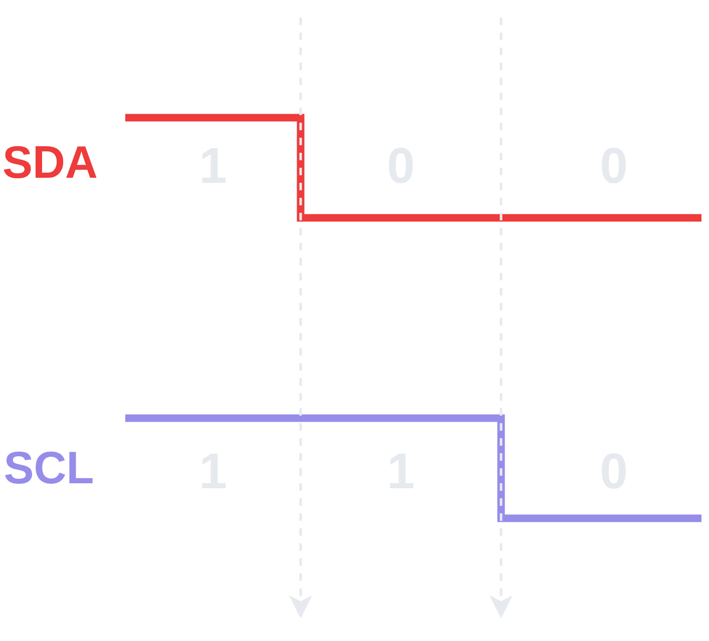- The “`START`Condition” occurs when`SDA`is pulled low when`SCL`is still`HIGH`\.
- After the “`START`Condition” occurs,`SCL`is pulled`LOW`and the transaction begins\.
### Stop Condition
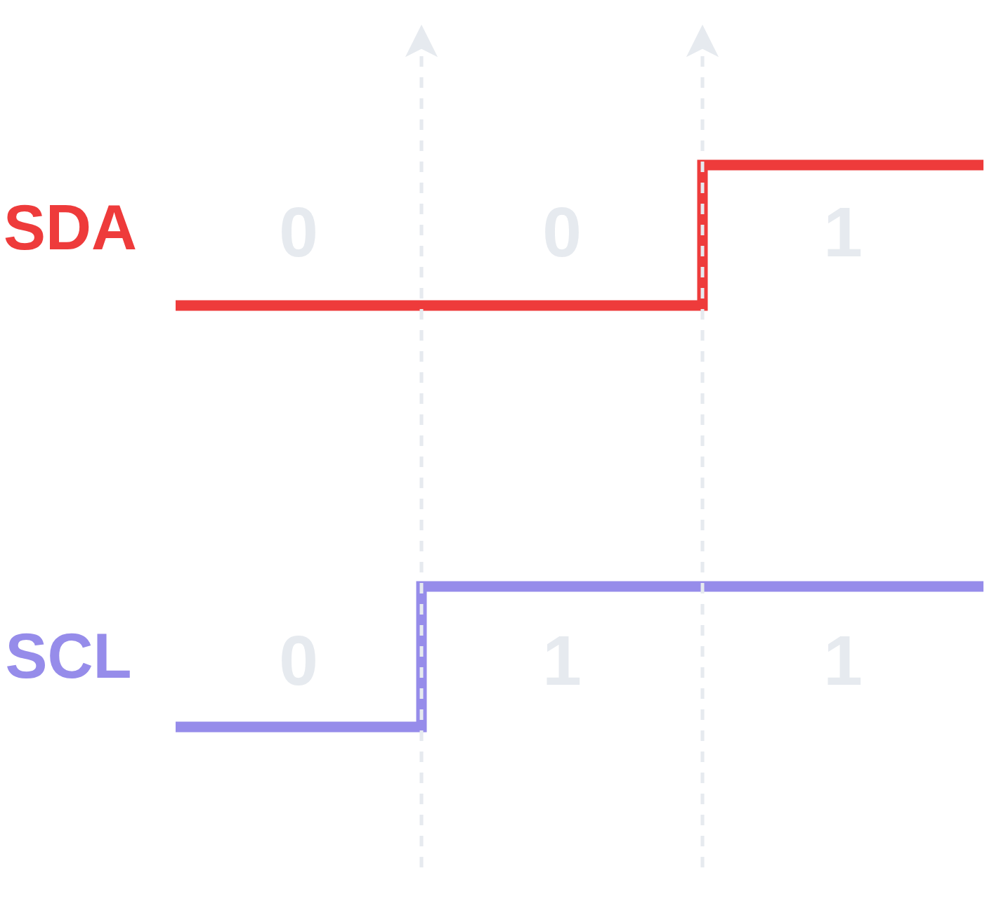- The “`STOP`Condition” occurs when`SDA`is released to`HIGH`when`SCL`is also`HIGH`\.
- After the “`STOP`Condition” occurs, the transaction is complete and the I2C bus is free to be claimed\.
## Clock Stretching
- “Clock Stretching” is a mechanism that allows a target device to pause an I2C transaction by holding`SCL``LOW`\.
- Normally the controller is in control of the clock`SCL`, it drives and the target responds\.
- Because both lines are open\-drain, a target can hold`SCL``LOW`to pause the controller\.- If the controller goes to release`SCL`to high to start the next clock pulse, but the target is holding it`LOW`, then`SCL`stays low\. - The controller is designed to check whether`SCL`actually went`HIGH`before proceeding, if it sees that`SCL`did not go`HIGH`, it waits\. - The target holds`SCL``LOW`for as long as it needs and then releases it to`HIGH`, allowing the transaction to proceed as usual\.
- Target may use “Clock Stretching” when it needs additional time to process or prepare data\.
> Note that not all I2C controllers support clock stretching\. Using a target that stretches the clock can cause issues when the controller doesn’t support it\.
## Frame
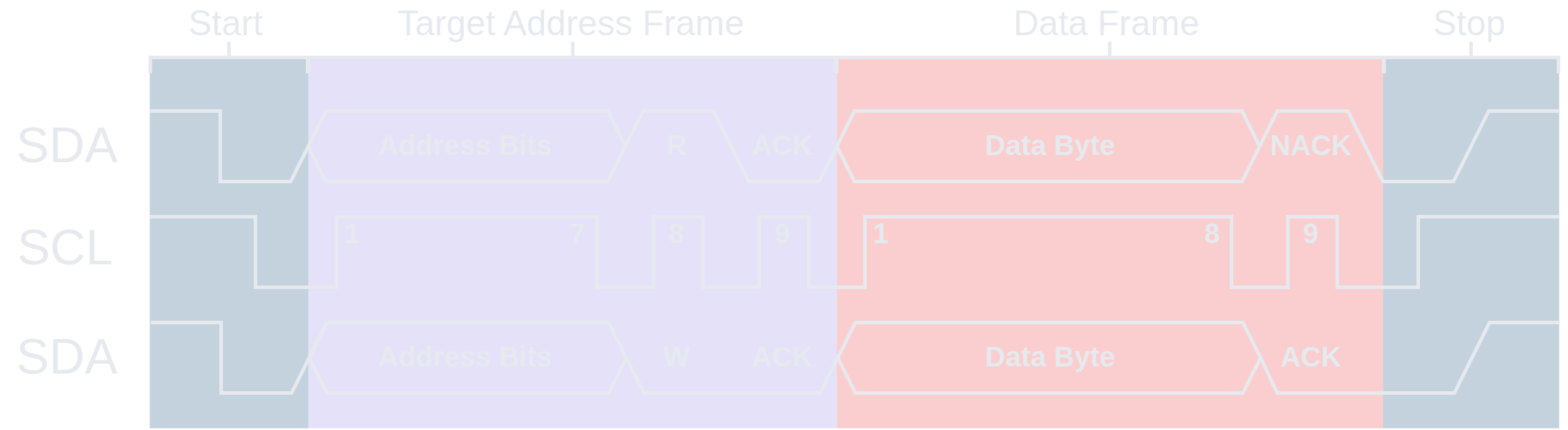- A “Frame” can be defined as the basic unit of transmission in the I2C protocol, always comprised of 9 bits where the last bit is an`ACK/NACK`bit\.
- The term “Frame” isn’t really “official” or used by the I2C spec, but is often used when making sense of I2C and talking about it\.
- There are two kinds of frames that, while both being comprised of 9 bits, have slightly different anatomy for the 1st byte of the frame:1. Target Address Frame 2. Data Frame
## Target Address Frame
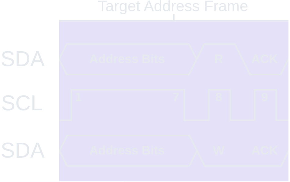- The “Target Address Frame” is always the*first*frame to appear in any I2C transaction\.
- It determines which target will participate in the transaction and what kind of transaction will occur \(Read/Write\)\.
### Target Address
- The first 7 bits of the “Target Address Frame” is the “Target Address”\.
- Each target on I2C must have a fixed address\.
- Addresses are normally 7 bits long \(less commonly, 10 bits\) with MSB \(Most Significant Bit\) first\.
- Addresses are hardcoded for devices and may be \(partially\) configurable via external address lines or jumpers\.- For example, the MPU\-6050 has a default I2C address of`0x68`, but can be configured to`0x69`by soldering the jumper on the device\. - This can be useful and desirable for providing unique addresses if you want multiple of the same device on an I2C bus in order to distinguish them as two distinct targets\.
- Because addresses are 7 bits, the range for these addresses is 128 unique addresses from`0x00`to`0x7F`\.- In reality a handful of these are reserved by the I2C specification\.
### R/W Bit
- The 8th bit in the “Target Address Frame” is the “R/W Bit”\.
- An I2C transaction can either be a “Read” or “Write”\. This is decided by setting the “R/W Bit”\.- `READ`: 1 \(released`HIGH`\) - `WRITE`: 0 \(pulled`LOW`\)
### ACK/NACK Bit
- The 9th \(last\) bit in the “Target Address Frame” is the “`ACK/NACK`Bit”\.
- The`ACK/NACK`in the “Target Address Frame” is*always*set by the target\.
## Data Frame
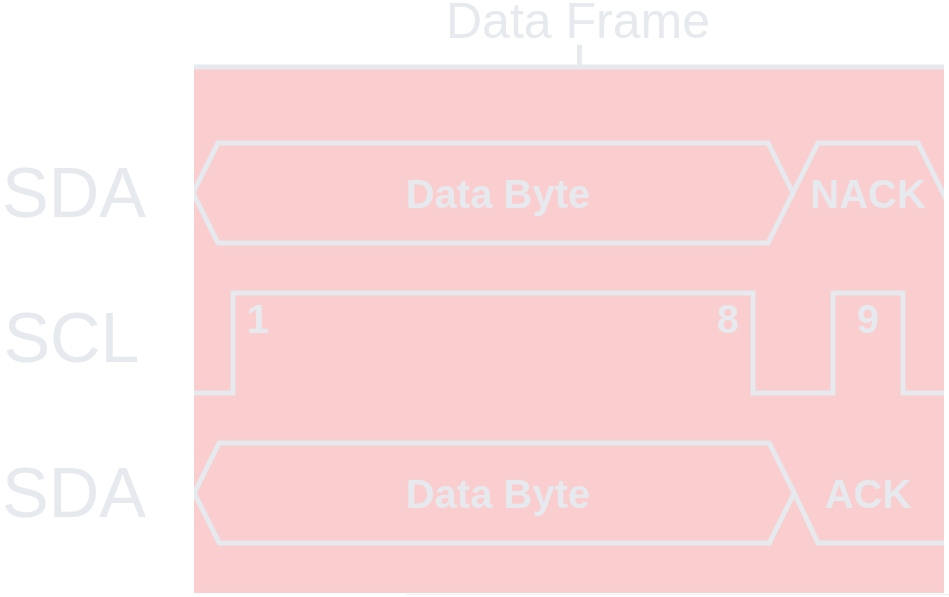- The “Data Frame” contains the actual data payload of the I2C transaction\.
- The first “Data Frame” in an I2C transaction always immediately follows the “Target Address Frame”\.
### Data Byte
- The “Data Byte” is 8 bits with MSB \(Most Significant Bit\) first and*is*the actual data payload\.
- As previously discussed, the data is sent by whoever the sender is \(controller or target depending on R/W bit\)\.> - Note that the`ACK/NACK`is set by the receiver but the “Data Byte” is set by the sender\.
- These data bytes may be all data, but often one of them will indicate an internal address or register location in the target device\.- For example, if the controller wants to write a certain value to a specific register in the target, the data byte might be the address or location of that register and the second data byte would be the actual data that is to be written to that location\.
- In many cases, multiple data bytes are sent in one I2C transaction\.- Additional bytes are simply concatenated onto the previous byte, with an`ACK`bit separating them\. This is illustrated better later\.
### ACK/NACK Bit
- The 9th \(last\) bit in the “Data Frame” is the “`ACK/NACK`Bit”\.
- Set by the receiver in the transaction\.
## Transaction
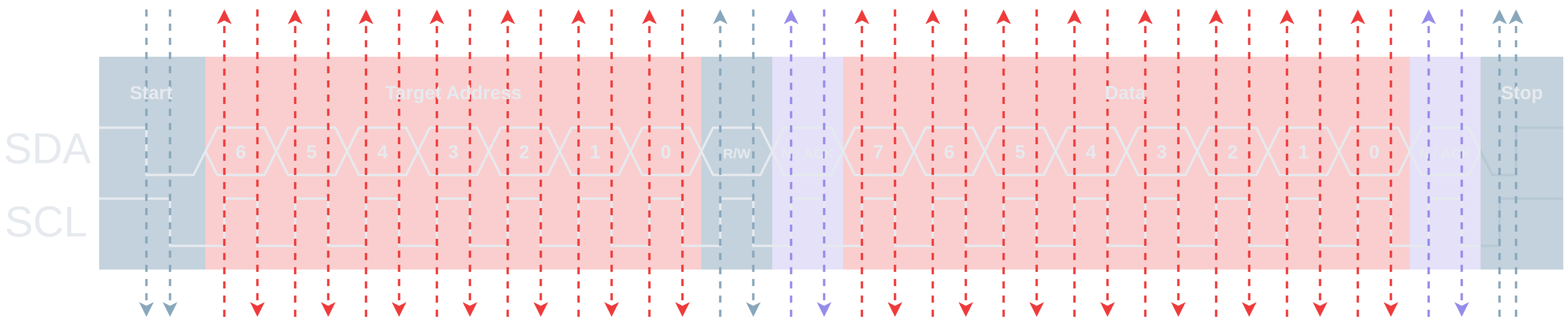- This diagram illustrates an I2C transaction at a glance\.
- A transaction always follows the same layout:1. Start Condition 2. Target Address Frame 3. Data Frame\(s\) 4. [Repeated Start](https://rana-emaan.com/read/notes/i2c/#repeated-start)\(Optional\) 5. Stop Condition
## Write
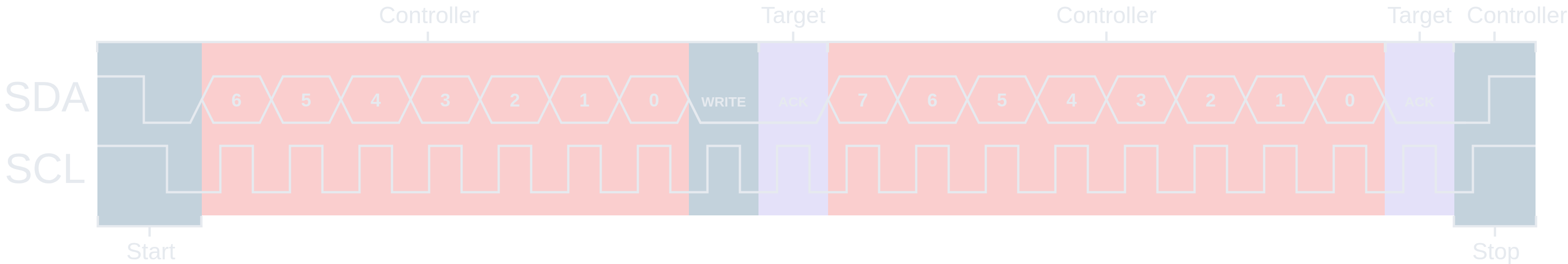- This diagram specifically illustrates an I2C “Controller`WRITE`” and depicts whether the controller or target has set a bit on the data line`SDA`\.
## Multiple Writes
`START`Target Addr\.`W``ACK`Data Byte`ACK`…Data Byte`ACK``STOP`> Note that in contrast to the “Multiple Reads”, in a string of`WRITE`s, the target is the setter of the`ACK/NACK`bit, and it does*not*terminate the srting of`WRITE`s with a`NACK`, it just`ACK`s and`STOP`s\.
## Code
```
#define MPU6050_ADDRESS 0x68
#define TICKS (1000 / portTICK_PERIOD_MS) // 1 Second
void write(uint8_t reg, uint8_t data) {
i2c_cmd_handle_t cmd = i2c_cmd_link_create(); // Command Queue
i2c_master_start(cmd); // Start Condition
i2c_master_write_byte(cmd, (MPU6050_ADDRESS << 1) | I2C_MASTER_WRITE, true) // Target Address Frame w/ ack_en = true
i2c_master_write_byte(cmd, reg, true); // Data Frame w/ ack_en = true
i2c_master_write_byte(cmd, data, true); // Data Frame w/ ack_en = true
i2c_master_stop(cmd); // Stop Condition
i2c_master_cmd_begin(I2C_NUM_0, cmd, TICKS) // Execute Commands
i2c_cmd_link_delete(cmd); // Free the memory allocated for Command Queue
}
```
## Read
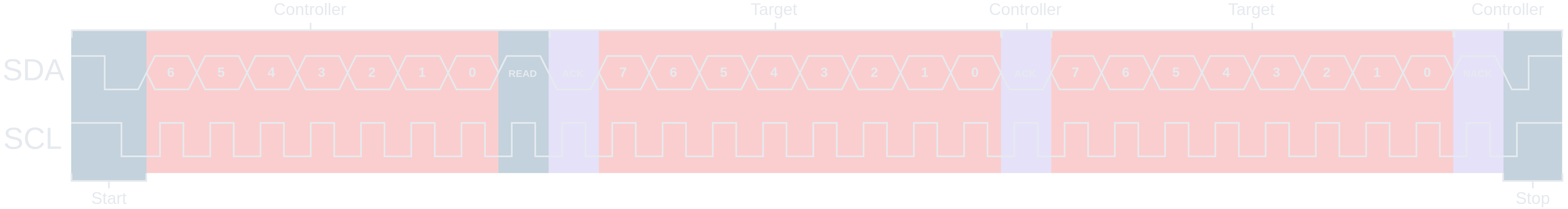- This diagram specifically illustrates an I2C “Controller`READ`” and depicts whether the controller or target has set a bit on the data line`SDA`\.
## Multiple Reads
`START`Target Addr\.`R``ACK`Data Byte`ACK`…Data Byte`ACK`Data Byte`NACK``STOP`> Note that in a string of`READ`s, the controller is the setter of the`ACK/NACK`bit, and it terminates the string of`READ`s with a`NACK`\.
## Code
```
#define MPU6050_ADDRESS 0x68
#define TICKS (1000 / portTICK_PERIOD_MS) // 1 Second
void read(uint8_t *buffer) {
i2c_cmd_handle_t cmd = i2c_cmd_link_create(); // Command Queue
i2c_master_start(cmd); // Start Condition
i2c_master_write_byte(cmd, (MPU6050_ADDRESS << 1) | I2C_MASTER_READ, true); // Target Address Frame w/ ack_en = true
i2c_master_read(cmd, buffer, 2, I2C_MASTER_LAST_NACK); // 2 Data Frames, ACK all but last which gets NACK
i2c_master_stop(cmd); // Stop Condition
i2c_master_cmd_begin(I2C_NUM_0, cmd, TICKS); // Execute Commands
i2c_cmd_link_delete(cmd); // Free the memory allocated for Command Queue
}
```
## Repeated Start
- A normal transaction is`START`→ Target Address → Data →`STOP`\.
- A “Repeated`START`” is when the controller issues another`START`without issuing a`STOP`first\.
- A “Repeated`START`” is only needed when switching transaction directions \(Read/Write\), otherwise you just concatenate data frames in the same transaction\.
- “Repeated`START`” allows the controller to maintain control over the bus without the risk of losing it to another controller if it had to`STOP`and then try to`START`again\.
- “Repeated`START`” lets you chain two transactions together atomically without ever releasing the I2C bus between them\.
## Example
- A classic example is read\-from\-register:1. From the target’s datasheet, we know what register on the target we are interested in reading data from\. 2. So we need to tell the target which register that is by writing the register address to the target’s internal register pointer \(tell it where to read from\)\. 3. Then the target can read the data at that register address and tell us what is there such as sensor data\.
- If you did`STOP`then`START`between these, another controller could claim the I2C bus in the window between them and issue its own transaction to the same target\.- That new transaction could write to the target’s internal register pointer, changing it to point a different register entirely\. - Then when the other controller reclaims the I2C bus and tries to do its`READ`phase, it would be reading from the wrong register without knowing it\. - Repeated`START`keeps the whole operation atomic by never releasing the bus between the two phases\.
## Code
```
#define MPU6050_ADDRESS 0x68
#define MPU6050_ACCEL_XOUT_H 0x3B
#define TICKS (1000 / portTICK_PERIOD_MS) // 1 Second
void read_register(uint8_t reg, uint8_t *buffer, size_t len) {
i2c_cmd_handle_t cmd = i2c_cmd_link_create(); // Command Queue
// Write Phase - Tell the target which register to read from
i2c_master_start(cmd); // Start Condition
i2c_master_write_byte(cmd, (MPU6050_ADDRESS << 1) | I2C_MASTER_WRITE, true); // Target Address Frame w/ ack_en = true
i2c_master_write_byte(cmd, reg, true); // Data Frame (Register Address) w/ ack_en = true
// Read Phase - Repeated Start to switch direction
i2c_master_start(cmd); // Repeated Start Condition
i2c_master_write_byte(cmd, (MPU6050_ADDRESS << 1) | I2C_MASTER_READ, true); // Target Address Frame w/ ack_en = true
i2c_master_read(cmd, buffer, len, I2C_MASTER_LAST_NACK); // len Data Frames, ACK all but last which gets NACK
i2c_master_stop(cmd); // Stop Condition
// Execute
i2c_master_cmd_begin(I2C_NUM_0, cmd, TICKS); // Execute Commands
i2c_cmd_link_delete(cmd); // Free the memory allocated for Command Queue
}
void app_main(void) {
uint8_t raw[6]; // Buffer
read_register(MPU6050_ACCEL_XOUT_H, raw, 6);
int16_t ax = (raw[0] << 8 | raw[1]); // Accelerometer X
int16_t ay = (raw[2] << 8 | raw[3]); // Accelerometer Y
int16_t az = (raw[4] << 8 | raw[5]); // Accelerometer Z
}
```