Cached at:
07/05/26, 10:34 PM
# Cursed circuits: capacitance multiplier
Source: [https://lcamtuf.substack.com/p/cursed-circuits-capacitance-multiplier](https://lcamtuf.substack.com/p/cursed-circuits-capacitance-multiplier)
Electronic circuit theory is a[frequent theme](https://lcamtuf.substack.com/p/electronics-curriculum)on this blog\. As a part of this*sorta\-*curriculum, I published a number of articles about operational amplifiers\. I keep coming back to this topic for two reasons\. First, I think these components are usually explained poorly, making them a major stumbling block for folks trying to learn the craft\. Second, op\-amps have gotten really good, inexpensive, and small, so I think they should be used more\.
If the component is still a mystery to you, this article is probably not the best place to start; we’ll cover the very basics, but I recommend carving out some time to go over two other write\-ups from 2023:
[](https://lcamtuf.substack.com/p/the-basics-of-signal-amplification)
[](https://lcamtuf.substack.com/p/whats-in-an-op-amp)
I also cover op\-amp theory \(and a lot more\!\) in*[The Secret Life of Circuits](https://lcamtuf.coredump.cx/electronics/)*, a lovingly\-crafted book that’s available in early access and will be hitting the shelves in about two months\.
Today, I’d like to talk about a circuit that didn’t make the cut for the book\. It’s not nearly as useful as a[transimpedance amplifier](https://lcamtuf.substack.com/p/building-a-decent-microphone-amplifier), an[integrator](https://lcamtuf.substack.com/p/cursed-circuits-3-true-mathematics), or a[Sallen\-Key filter](https://lcamtuf.substack.com/p/analog-filters-part-2-let-it-ring), all of which get in\-depth treatments from first principles\. At the same time, it’s just too cool not to share\.
I know that most readers don’t click links, so before we dive in, let’s recap what an op\-amp does\. If you have it pegged as some sort of a variable\-gain amplifier that “reads” the value of a pair of external resistors to configure internal gain, it’s bet to forget all that and start afresh\.
An ideal op\-amp does one thing and one thing only: it calculates the difference between the voltages on its two input pins \(*Vin\-*and*Vin\+*\), multiplies it by a humongous constant factor*\(AOL*, typically 1,000,000 or more\), and then outputs the resulting voltage in relation to the midpoint of the supply \(*Vmid*\)\. We can write this as:
\\\(V\_\{out\} = V\_\{mid\} \+ \(V\_\{in\+\} \- V\_\{in\-\}\) \\cdot A\_\{OL\}\\\)
In practical terms, it means that if*Vin\-*is noticably less than*Vin\+*, the output voltage swings toward the positive supply of the chip; conversely, if*Vin\-*exceeds*Vin\+*, the output swings dives toward the negative rail\. Intermediate output voltages are possible only in a very narrow, microvolt\-range linear region of*Vin\-*≈*Vin\+*\.
The simplest op\-amp circuit — and the only one we need today — is the voltage follower:
[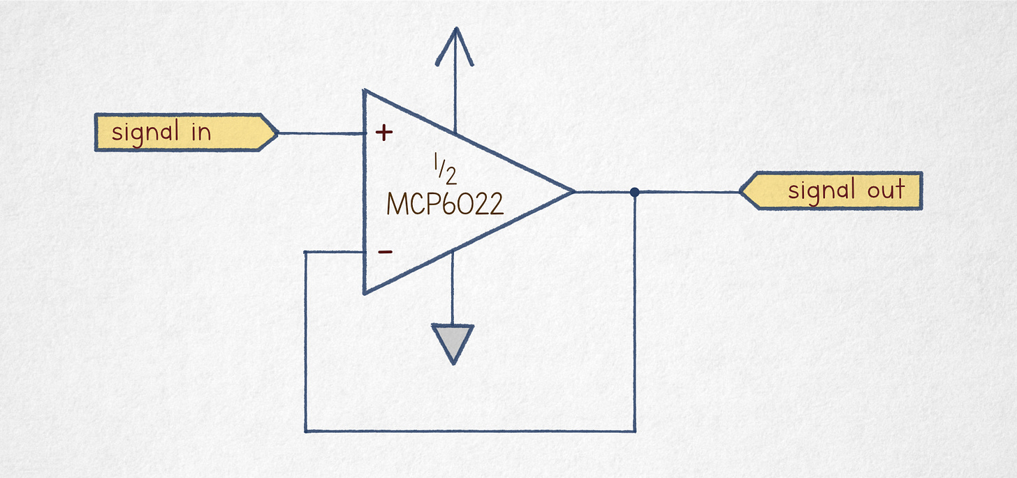](https://substackcdn.com/image/fetch/$s_!A-DN!,f_auto,q_auto:good,fl_progressive:steep/https%3A%2F%2Fsubstack-post-media.s3.amazonaws.com%2Fpublic%2Fimages%2Fb0b7688d-6566-4a86-bcbf-f375139c030b_1700x800.jpeg)*A simple voltage follower\.*
The circuit loops the output voltage onto one of its differential input pins\. If the input signal on*Vin\+*creeps higher in relation to*Vin\-*, this makes the amplified differential signal more positive, forcing the output voltage to rise until the*Vin\-*≈*Vin\+*equilibrium is restored\. In the same vein, if*Vin\-*drops, the difference becomes more negative, sending the amplified signal toward a lower equilibrium point\. In effect, the output voltage tracks the input signal with sub\-millivolt accuracy\.
To make sense of the next section, we need just two other tidbits of electronic theory\. First, Ohm’s law: the current flowing through a resistor is proportional to the electromotive force \(voltage\) applied to its terminals, divided by the component’s value \(resistance\): I = V/R\. Second, we need to know that a capacitor subjected a voltage across its terminals will admit \(nearly\-arbitrary\) charging current until the pushback force created by the accumulated charge matches the external voltage\. Higher component value \(higher capacitance\) means that proportionately more electrons can be shuffled around in response to the same electromotive force; in other words, higher*C*means more current over time\.
*If the above paragraph sounds confusing, you should review the article on[core concepts in electronic circuits](https://lcamtuf.substack.com/p/primer-core-concepts-in-electronic)before venturing forth\.*
This brings us to our guest of honor: the capacitance multiplier\. It’s the kind of a circuit that usually doesn’t make sense at first glance because we can’t pattern\-match it to anything we know:
[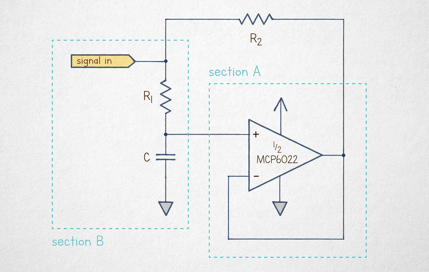](https://substackcdn.com/image/fetch/$s_!qMWu!,f_auto,q_auto:good,fl_progressive:steep/https%3A%2F%2Fsubstack-post-media.s3.amazonaws.com%2Fpublic%2Fimages%2Fd86dcd7c-184a-497d-8b97-32936641ad40_2050x1300.jpeg)*A basic capacitance multiplier\.*
To unravel the mystery, it suffices to break it down into two mostly\-separate building blocks\. Section A is just an op\-amp configured as a voltage follower\. No matter what else is going in the circuit, it takes some voltage from section B and then mirrors that signal on its output leg\.
Section B is a capacitor that’s charging through a resistor; although the voltage across the capacitor’s terminals \(*Vcap*\) will change over time, let’s model this in a freeze\-frame view\. In this setting, the op\-amp is mirroring the capacitor’s current charge state; the voltage on the right terminal of*R2*is almost exactly the same as*Vcap*\.
Moving onto*R1,*we can conclude from Ohm’s law that the current flowing through the resistor depends only on the component’s value and the momentary voltage across its terminals\. No matter what else is going in the circuit, the upper terminal of*R1*is at the same voltage as the input leg \(*Vsignal*\) and the lower terminal is always at*Vcap\.*Therefore, the resistor current is:
\\\(I\_\{R1\} = \\frac\{V\_\{signal\} \- V\_\{cap\}\}\{R1\}\\\)
For clarity, let’s shorten the*Vsignal \- Vcap*expression to*v\.*This gives us:
\\\(I\_\{R1\} = \\frac\{v\}\{R1\}\\\)
Next, let’s have a look at the other resistor,*R2*\. The component’s left terminal is at*Vsignal*; the right terminal must be at*Vcap*by the operation of the voltage follower\. This means that the current flowing through the resistor is just:
\\\(I\_\{R2\} = \\frac\{v\}\{R2\}\\\)
In essence, we have two resistors in parallel between the input leg and*Vcap*\.
Naturally, the currents through the resistors are flowing in the same direction\. If*Vsignal*\>*Vcap*, the current flows in via the input terminal\. In the inverse case, it feeds back into the signal supply\. In both cases, the total input current is:
\\\(I\_\{total\} = I\_\{R1\} \+ I\_\{R2\} = \\frac\{v\}\{R1\} \+ \\frac\{v\}\{R2\} = \\frac\{\(R2 \+ R1\) \\cdot v\}\{R1 \\cdot R2\} \\\)
Next, let’s calculate the ratio of*Itotal*to the current actually diverted to the capacitor via*R1*\. We’ll label this ratio*n:*
\\\(n = \\frac\{I\_\{total\}\}\{I\_\{R1\}\} = \\frac\{\(R2 \+ R1\) \\cdot \\cancel\{v\}\}\{\\cancel\{R1\} \\cdot R2\} \\cdot \\frac\{\\cancel\{R1\}\}\{\\cancel\{v\}\} = 1 \+ \\frac\{R1\}\{R2\}\\\)
This tells us that the capacitor is charging*n*times more slowly than it would if the circuit consisted just of the passive R\-C layout in section B\. Another way to look at it is that the situation is indistinguishable from charging a proportionately larger capacitance —*n ·*C — through a pair of parallel resistors*R1*and R2\. If R1 ≫ R2, this can be approximated as a model of*n ·*C charging via*R2*\.
And that’s it: you can turn a cheap 1 µF capacitor into a fancy 1 mF by tossing in an op\-amp and two resistors with carefully\-chosen values\. The circuit doesn’t emulate increased energy storage — you can’t use this for backup power — but in applications such as signal filtering or timekeeping, it’s notionally a pretty neat trick\. You can use components that are smaller, cost less, and have better specs\.
In practice, it’s is less useful than it used to be\. Capacitor technology has improved dramatically over the past 20\-30 years\. And if you truly need an ultra low\-frequency filter or a long\-interval timer, chances are, the same idea can be realized with greater flexibility and fidelity with a digital chip\.
Still — it’s neat, right?
As a voluntary homework assignment, consider the following variant of the earlier design:
[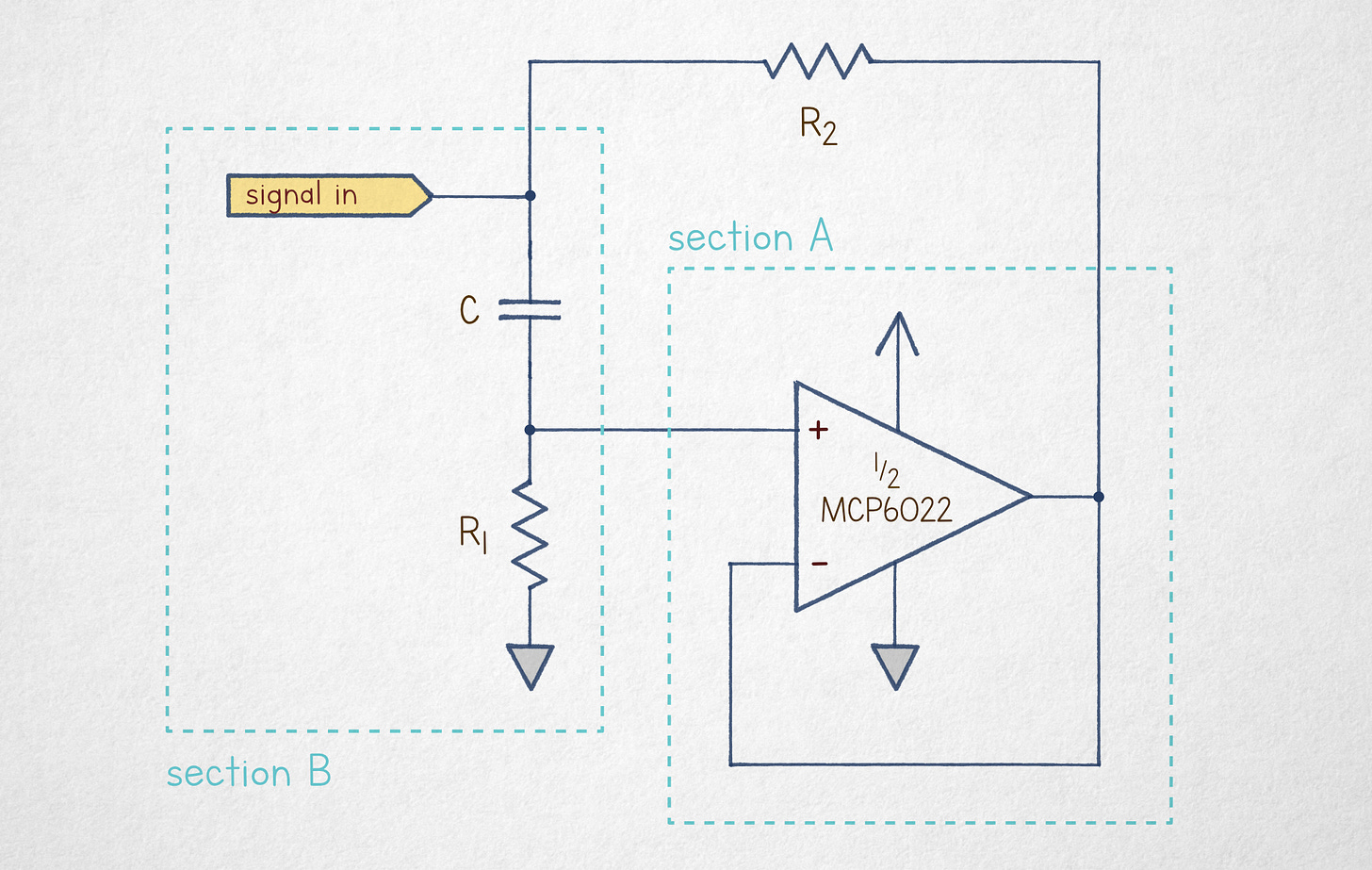](https://substackcdn.com/image/fetch/$s_!m7a3!,f_auto,q_auto:good,fl_progressive:steep/https%3A%2F%2Fsubstack-post-media.s3.amazonaws.com%2Fpublic%2Fimages%2F1f1c6141-cde1-405a-9933-389dec73d0d8_2050x1300.jpeg)*Umm… a… sorta\-inverse capacitance multiplier?*
The only change is that*C*and*R1*are swapped\. Your mission, should you accept it, is to figure out what this circuit does\.
If you’re stumped, note that for a capacitor to charge, there must be a matching motion of charges on*both*terminals — i\.e\., some current must flow “through” the component\. In the circuit, if the capacitor is initially discharged and the input voltage suddenly jumps to 5 V, the charging process is hindered by*R1*, so the voltage across the capacitor stays near 0 V; the electromotive force simply couples across the dielectric gap, putting*Vin\+*at 5 V \- 0 V\. It’s only after a while that a sufficient number of electrons can make its way through R1, nudging*Vcap*toward 5 V and*Vin\+*toward 0 V\.
*Some of the earlier articles in this series:*
[](https://lcamtuf.substack.com/p/cursed-circuits-charge-pump-voltage)
[](https://lcamtuf.substack.com/p/cursed-circuits-2-switched-capacitor)
[](https://lcamtuf.substack.com/p/cursed-circuits-4-pll-frequency-multiplier)
*I write about electronics,[the foundations of mathematics](https://lcamtuf.substack.com/p/monkeys-typewriters-and-busy-beavers),[the history of technology](https://lcamtuf.substack.com/p/a-brief-history-of-counting-stuff), and other geek interests\. If you like it, please subscribe\.*
#### Discussion about this post
### Ready for more?